What's the difference between a RF Band-reject and Band-pass (YIG) Filter?
1. YIG RF Bandpass Filters:
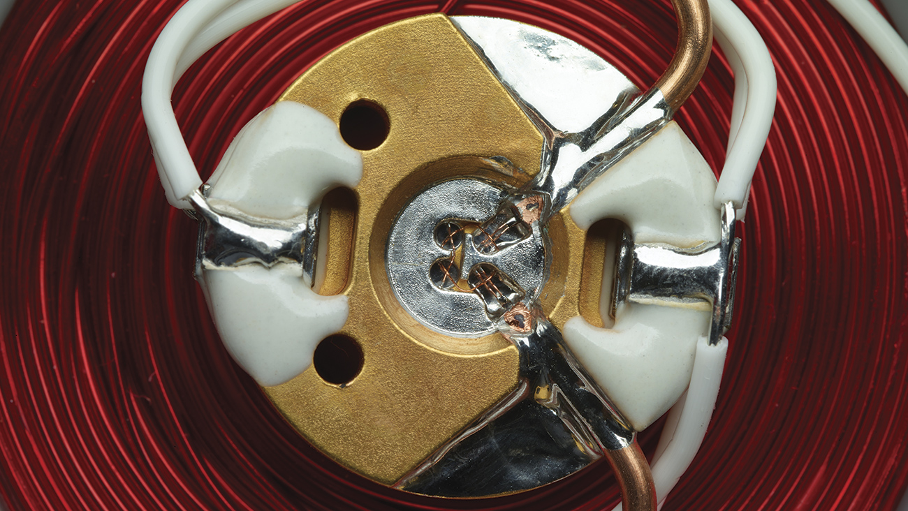
In an RF bandpass filter, the coupling loops are aligned at a 90° angle to prevent direct RF coupling. One end of each loop is grounded. This prevents the filtered signal from being reflected.
The RF input signal of the coupling loop modulates the magnetic field around the YIG sphere, this modulation is coupled to the magnetic field resonating around the YIG sphere, which then couples to the second/output loop. The RF signal passing through the filter must be the same frequency as the RF magnetic field resonating around the YIG sphere.
The frequency bandwidth/spectrum that is coupled through the YIG resonator is dependent on the spacing between the YIG resonator and the coupling loop. The closer the loop, the wider the bandwidth. Bandwidth can also be expanded by increasing the number of YIG resonators and carefully “tuning” the RF coupling loops. Filter insertion loss increases with expanded bandwidth.
A YIG bandpass filter’s 3 dB bandwidth expands as the filter is tuned to higher operating frequencies at a rate of approximately 20% per octave (e.g. 30 MHz @ 2 GHz, 50 MHz @ 18 GHz).
Micro Lambda’s standard YIG bandpass filter’s 3 dB bandwidth is 15 MHz to 40 MHz ( @ 2 GHz); 20 MHz to 50 Mhz ( @ 18 GHz). Filters with 3 dB bandwidths greater than 500 MHz are available above 6 GHz operating frequency.
There is a limit (i.e. Limiting) on the total amount of RF energy that a YIG resonator/sphere can couple/ transfer (e.g. 0 dBm to +10 dBm).
2. YIG RF Band Reject Filters:
YIG RF Band Reject Filters resonate in a two stage sphere but there is only one coupling loop (ribbon) per YIG sphere. The coupling loops are aligned along a straight line and are interconnected between the YIG resonators.
The coupling loops are essentially RF transmission lines that pass all RF energy. However, when these transmission lines are located close to the surface of the YIG sphere, the loop couples to the magnetic field resonating ( @ microwave frequencies ) around the YIG sphere.
This coupling essentially reflects/rejects in coming frequencies that are at the same RF frequency as the RF magnetic field resonating around the YIG sphere.
Rejection bandwidth is widened by increasing the number of YIG resonators and carefully “tuning” the RF coupling loops.
Micro Lambda’s standard band reject filter’s 40 dB rejection bandwidth is 15 MHz to 70 MHz.
Learn more by downloading our technical briefs under resources on our support page >>

