
Technical Brief Details YIG-tuned Bandpass and Band-reject Microwave Filters
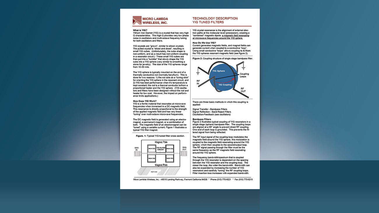
Using small conductive “loops” a YIG filter is coupled to and from a YIG spheres’ resonant magnetic field. The closer the loop, the wider the bandwidth. Bandwidth can also be expanded by increasing the number of YIG resonators and carefully “tuning” the RF coupling loops. In this brief, RF engineers will learn the three basic methods in which this coupling is applied: signal transfer; signal reflection; and oscillation feedback, and how this differentiates a bandpass from a band-reject filter.
Readers will also learn the limits (i.e. limiting) on the total amount of RF energy that a YIG resonator/sphere can couple/transfer (e.g. 0 dBm to +10 dBm). As the coupling loops are essentially RF transmission lines, when these transmission lines are located close to the surface of the YIG sphere, the loop couples to the magnetic field resonating around the YIG sphere. This coupling essentially reflects/rejects incoming frequencies that are at the same RF frequency as the RF magnetic field. Rejection bandwidth is widened by increasing the number of YIG resonators and carefully “tuning” the RF coupling loops.
The brief also details the four YIG filter specification groups: RF, magnet, power consumption and environmental conditions. A complete glossary of terms defines all key specifications one should look for in a fully spec’d microwave YIG filter.
To learn more, download the technical brief today >>

46515 Landing Parkway
Fremont, CA 94538
Tel: (510)770-9221
© 1990 - 2026, Micro Lambda Wireless, Inc. All Rights Reserved
Micro Lambda Wireless, Inc. | (510)770-9221 | 46515 Landing Parkway | Fremont, CA 94538